A feature that usual multimeters lack. For example, I have used it to measure the output of my DIY solar panel. They are inexpensive and easy to connect. These meters calculate current flow by the voltage drop across the shunt resistor. They have built-in shunts that should withstand measuring as much as 10 amperes.
How to Wire an Ammeter into a Car
You must see shunt behind your volt- and ammeter. That small bridge bent from a thick wire on PCB. If there is none- this guide is not for you. You need a wiring diagram with an external shunt instead. Also when measuring current that exceeds 10A which can be handled with the internal one. They are basically the same. There is a connector with thick wires and connector with thin wires. But coloring of wires vary.
Amperage measurement is done by passing power through thick wires. Power to the meter itself is fed through thin wires. You can use the same power supply where your measured load gets electricity. I tried this on the first one in the list. If someone has some other info please let me know. This exact one was in my original article. I have not tested this one myself. If someone can confirm this is correct I would be very thankful.
From the info I found from sellers and one youtube video- this one has a bit tricky coloring. Have you same kind of volt-ammeter?
Wiring basics
Full morning trying trying, result headache. Google to your website and bingo!! There is no longer voltage on the Blue wire.
- dating stock photos?
- Ammeter and Voltmeters.
- How do these ammeters work?.
- reykjavik dating site?
- How to Install a Car Volt Amp Gauge (with Pictures) - wikiHow.
- nashville online dating?
- Ammeter and Voltmeters.
Any advice truly appreciated mate. I always thought the amp meter should be on the live cable in series with the load? In this case is in series still but on the negative side?!
- How to wire digital dual display volt- and ammeter.
- dating cross pens?
- .
- best dating websites for seniors?
- best online dating sites france?
- .
- How to Wire an Ammeter into a Car | www.stavebninypovina.com.
- How to wire digital dual display volt- and ammeter - DIY Projects.
- .
It is now working mate. Thanks for taking an interest and trying to help. Excellent tutorial, with pictures that help in understanding. Thank you very much for providing such useful information. But keep in mind. If shunt is not built in, this diagram would be invalid and missing a shunt. Mentioning it just in case. Again, thank you very much for the detailed article and the fine clarification. It works like a charm!
Thank you very much, once again! That shold show that you can use this with external power supply since power supply must not be over 30V but measuring range is much bigger. My dual digital voltameter has red, black and green thick wires not the thin red and black to power the display. Chinese supplier unable to provide any advice or technical data. The display should obviously be in series with the load, but between which two terminals should the load be connected?
The third thick wire is obviously used to measure battery voltage of the circuit, but which wire should this be? Do you know if the ammeter can read both positive and negative current. I am pretty sure it only can measure one way. I would have to test this, but probably not. There is no place for minus sign anyway on the display.
As the one I am about to buy is specified to V and 10A it seems unbelievable. I mean, the amperage. Even the wire cross section looks too small for that, let alone the miniature connector the wires connected to.
My seller offers 4 other versions of the meter with different configurations, color, etc. I could not see anything like that on your drawing, neither my seller speaks about, so I am confused. Thanks, Laszlo Budapest, Hungary. Hi Janar, Thank you for posting the wiring diagram; I need it! I just received one of these fellahs. Purpose is to measure DC volts supplied to my model rail track. It would be nice to get a reading of amps supplied too.
I connected up as per your diagram. In my situation the power supply and the load to be read are one and the same, ie the 2 rails of the track. I get a correct volts reading, but the amps reading is 0.
Related Articles
No current is flowing trough there. Looks good, but mine came with different wire colors. Small red and black, then blue nearest the smaller wires , green then yellow. I found different sources with different answers. Looking at your pictures, my blue would be your large red aka positive polarity, but I cannot see the placement of the other 2.
I saw one place that said green was voltage detection but when I tried on a battery it sparked and meter went dark. Just to make sure I used just red and black and seems to still work ok, so this is just a pain.
Ammeter Gauge Wiring - Schema Wiring Diagrams
Could you explain how connect all five cables? I bought to of this meters and none are working, I made the connections like your pics. Connect a ground wire between the center ground terminal of the meter and a good engine ground. Leave the engine off and turn on the car's lights.
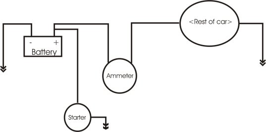
Your ammeter indicator should read negative. Disconnect your negative battery cable again and switch the wires on the back of the meter if the indicator reads positive. Start your engine and check your connections for hot spots with a multimeter. Use the brackets and nuts provided in your kit to attach it.