First thing we need to do is it insert the Liquid Crystal Library. We can do that like this: Then we have to create an LC object. In the loop we write our main program.
Complete Guide for Nokia LCD with Arduino | Random Nerd Tutorials
Using the print function we print on the LCD. The setCursor function is used for setting the location at which subsequent text written to the LCD will be displayed. The blink function is used for displaying a blinking cursor and the noBlink function for turning off. The cursor function is used for displaying underscore cursor and the noCursor function for turning off. Using the clear function we can clear the LCD screen. It is also possible to write a custom characters to the LCD. We can specify the appearance of each character by an array of 8 bytes. In the setup we have to create the custom character using the createChar function.
The first parameter in this function is a number between 0 and 7, or we have to reserve one of the 8 supported custom characters. The second parameter is the name of the array of bytes. We write the custom character to the display using the write function and as a parameter we use the number of the character. Inside a huge PCB factory: I highly appreciate that your video for LCD. The system cannot find the file specified. Not really, you can print something permanently, but sure you can make a code that would display what you want even after rebooting the LCD, for example, using the EEPROM of the Arduino which can store data when the power is off.
You need a resistor of Ohm, and you can increase the resistance of you want a dimmer backlight. I connected my resistor to a PMW port to control the backlight from the code. Have no experience with writing code but you have made it easier to understand the basics, TY Dejan! Yes, you can remove it, but you will need to set two resistors as a voltage dividers to get the proper voltage for getting the proper contrast of the LCD.
Currently you have JavaScript disabled. You can use these example sketches as a basis for developing your own code for the LCD display module. To access the example sketches perform the following steps: The sketch starts with a number of credits and a description of the required hardware hookup. In the beginning of the actual code we load the LiquidCrystal library. In the setup routine we initialize the LCD for 16 x 2, if you are using a different LCD module you would change this accordingly. As we did not specify the cursor location this will print at the beginning of the first row. In the beginning of the loop we set our cursor to the first position in the second row.
Note that the row numbers start with zero so the second row is row 1. We then use the millis function to print out every second milliseconds on the display. That ends the loop, so we start back at the top of the loop and repeat. The result will be a counter on the second line that counts seconds from the htime the Arduino was last reset. Load the sketch up to your Arduino and observe your display. The second example we will try is the Scroll sketch. In the loop the code demonstrates the use of the scrollDisplayLeft and scrollDisplayRight functions.
As their names imply they move the text in a left or right direction. In each case the functions are encased in a for-next counter, for each increment the text is scrolled one position in the appropriate direction. There are three such counters. The first one scrolls the text left by 13 positions, which is enough to move it off the display to the left. The second counter moves the text 29 positions to the right, which will bring it back onto the display and then move it off to the right. Finally the last counter moves the text 16 positions to the left again, which will restore it back to the center of the display.
- dating barrow in furness cumbria.
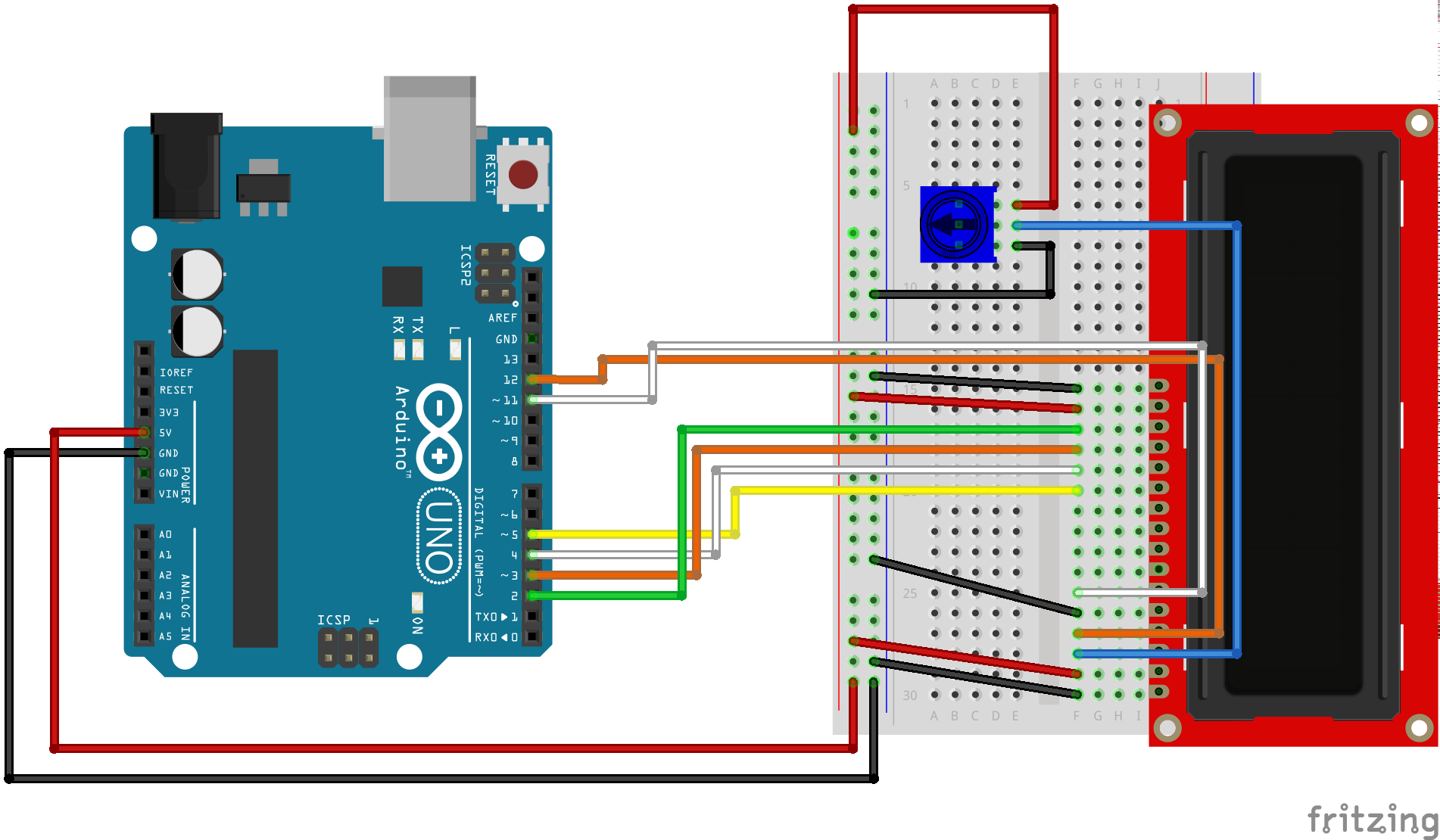
- Circuit Schematic.
- funny online dating messages that work.
- Using LCD Displays with Arduino.
- Complete Guide for Nokia 5110 LCD with Arduino.
The loop then repeats itself. One final sketch to look at is the Custom Character sketch, as it illustrates an important concept. Custom characters are useful when you want to display a character that is not part of the standard character ASCII character set. Thi scan be useful for creating custom displays for your project. A character on the display is formed in a 5 x 8 matrix of blocks so you need to define your custom character within that matrix.
Interface an LCD with an Arduino
You are limited to defining a maximum of eight characters. To use createChar you first set up an array of bytes with 8 elements. Each element in the array defines one row of the character in the 5 x 8 matrix. You then us e createChar to assign a number from 0 to 7 to that array. The Custom Character demonstration requires one additional component to be wired to the Arduino, a potentiometer 10K or greater wired up to deliver a variable voltage to analog input pin A0. Once you have that wired up you can proceed to load the sketch, examine it and then try it out.
As with the previous sketches we examined this one starts by loading the LiquidCrystal library and defining an object called lcd with the connection information for the display. It then moves on to define the custom characters. Each character is defined as an array with 8 elements, the zeros and ones in the array indicate which elements in the character should be on and which ones should be off.
Five arrays are defined, although the sketch actually only used four of them. This is done to show how we can animate a character on the display. The setup begins by defining the size of the LCD display, just as the previous sketches did. Then the five custom characters are assigned a unique integer using the createChar function. Remember, you can define a maximum of eight custom characters in a sketch. Finally the setup routine ends by printing a line to the first row of the LCD display.
"Hello World!"
This is optional for the other custom characters. We begin by reading the value of the voltage on pin A0 using the Arduino analogRead function. As the Arduino has a bit analog to digital converter this will result in a reading ranging from 0 to We then use an Arduino map function to convert this reading into a range from to This value is then assigned to an integer called delayTime , which as its name implies represents a time delay period.
First we set the cursor to the fifth position on the second row. We then draw our character with his or her? Next we delay by the amount of time specified by the delayTime variable.
- dating websites for 5th graders.
- Components needed for this Arduino LCD Tutorial.
- most accurate dating scan.
Remember this value is determined by the position of the potentiometer. We then draw the character with arms up. And we repeat the same delay. This is the end of the loop so we go back to the top and do it all again. The end result is that our character wil wave his arms up and down at a speed determined by the position of the potentiometer. Load the sketch and give it a run. Experiment with turning the controls and watch the little stick person in action! One thing you may have noticed about using the LCD display module with the Arduino is that it consumes a lot of connections.
But there is another solution. It was developed by Philips Semiconductors in for use in the television industry. The bus has evolved to be used as an ideal method of communicating between microcontrollers, integrated circuits, sensors and micro computers. You can use it to allow multiple Arduinos to talk to each other, to interface numerous sensors and output devices or to facilitate communications between a Raspberry Pi and one or more Arduinos.
The bus only uses four connections, two of them are for power: In I2C communications there is the concept of Master and Slave devices. There can be multiples of each but there can only be one Master at any given moment. In most Arduino applications one Arduino is designated Master permanently while the other Arduinos and peripherals are the Slaves. The Master transmits the clock signal which determines how fast the data on the bus is transferred. There are several clock speeds used with the I2C bus.
The original design used KHz and KHz clocks. Faster rates of 3.
Arduino LCD Tutorial
For most Arduino designs a KHz clock frequency is used. Every device on the I2C bus has a unique address. When the Master wants to communicate with a Slave device it calls the Slaves address to initiate communications. These pins are meant to be connected directly to the pin connection on the LCD display or onto other displays that use the same connection scheme. The device also has a 4-pin connector for connection to the I2C bus. In addition there is a small trimpot on the board, this is the LCD display brightness control.
Most of these devices have three jumpers or solder pads to set the I2C address. This may need to be changed if you are using multiple devices on the same I2C bus or if the device conflicts with another I2C device.